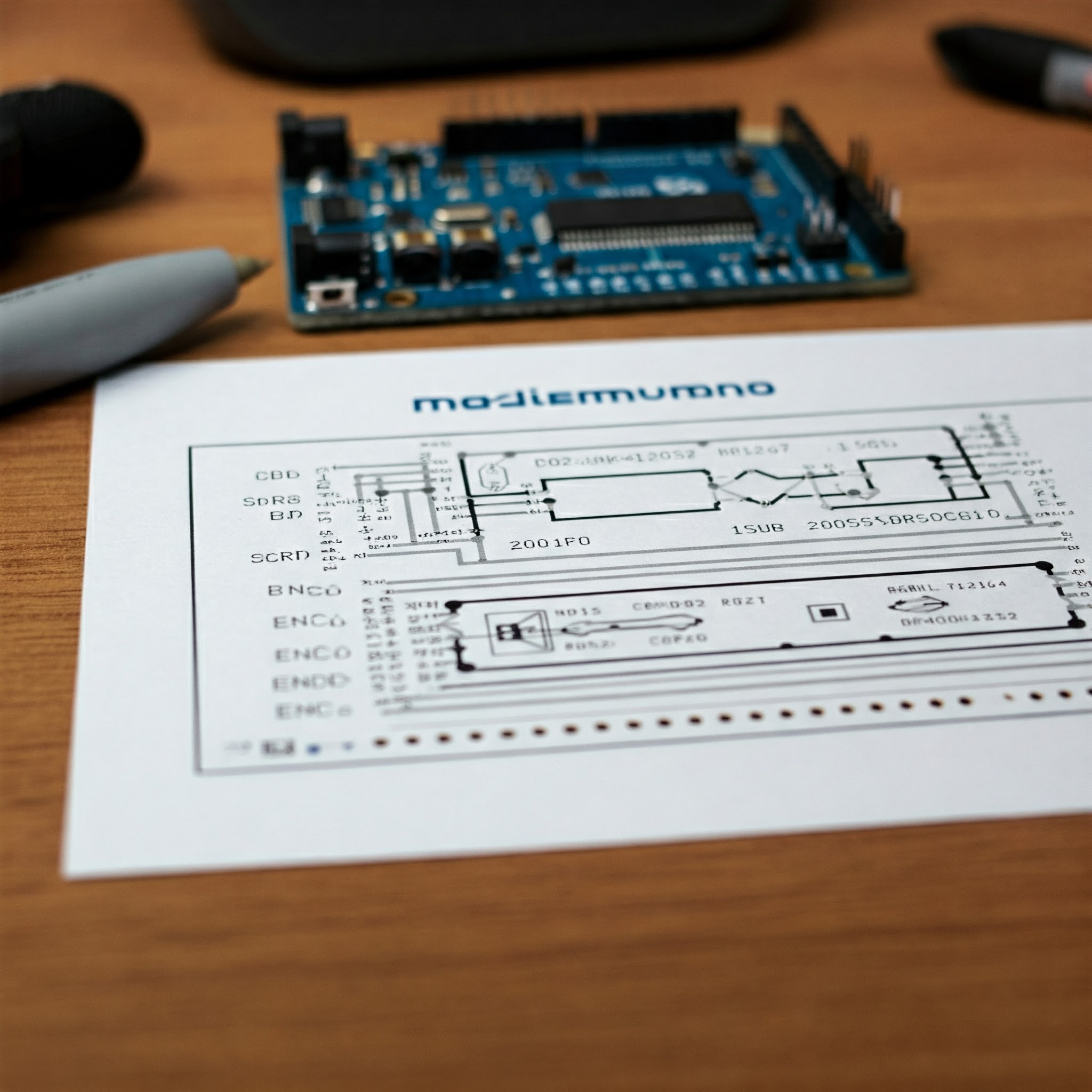
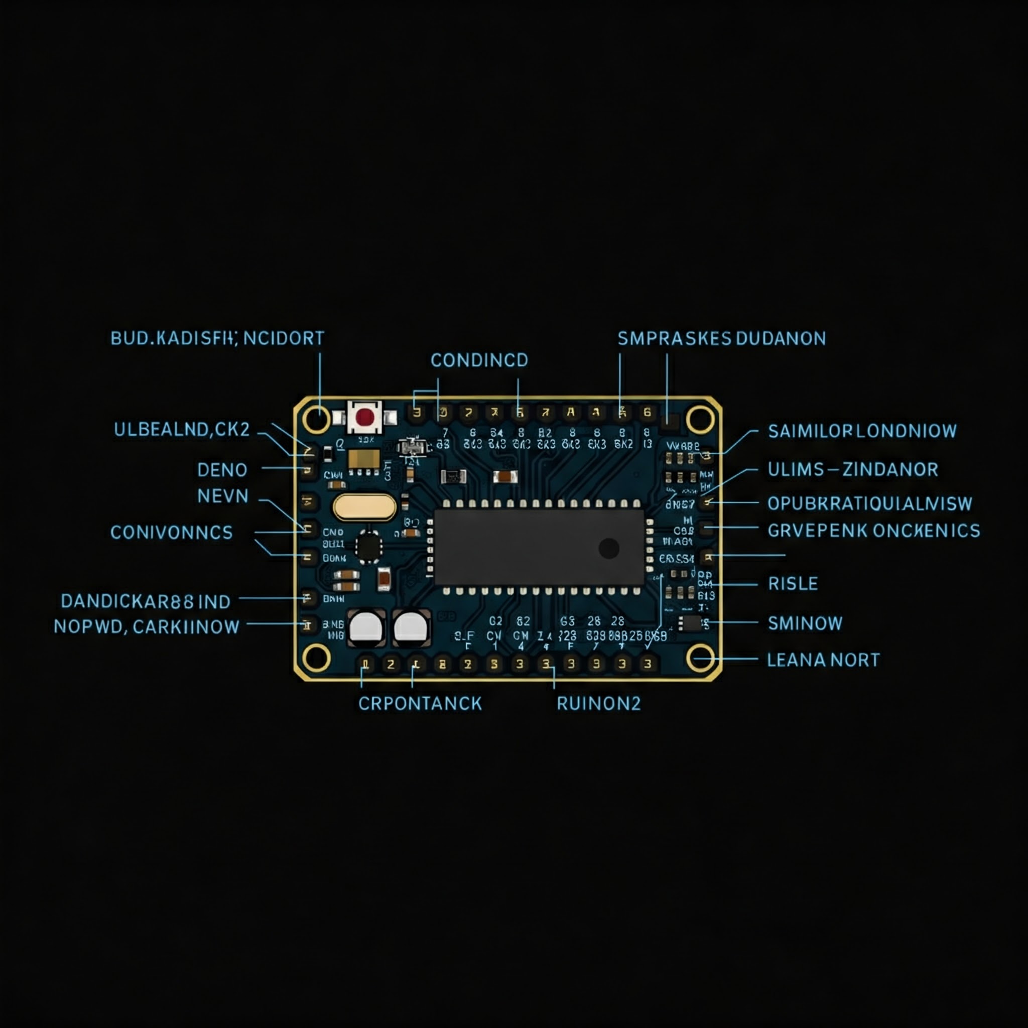
The Arduino Nano Pinoutsimplifies and accelerates electronics development. Standardized layout for the connection of various components. Knowledge about this proposition promotes efficient design processes. The Nano Board has a dedicated function for each of its pins. A solid understanding of this knowledge is crucial to maximize device performance. The diagram of pinout makes complex connections clear. These insights are clear and save us precious development time, also preventing potential errors. The knowledge of pinout makes us take creative discovery and realize new project.
What Is Arduino Pinout?
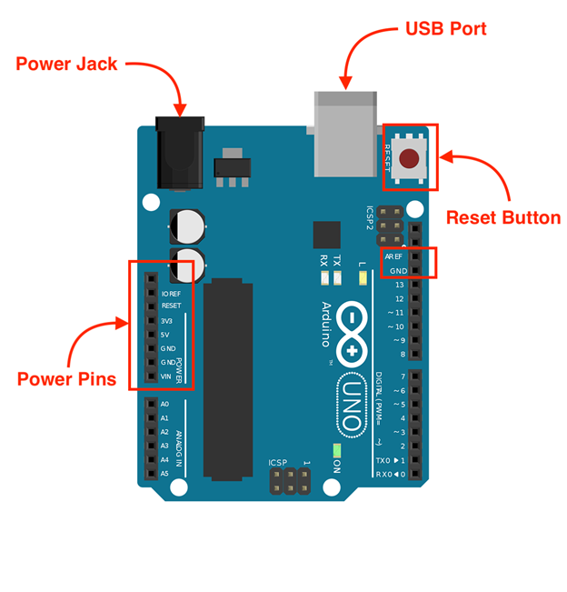
The Arduino Nano pinout diagram comprehensively illustrates the functionality of each pin. When constructing a circuit, this diagram allows the proper connections to be made. Pulse Width Modulation (PWM) applications are accommodated in designated pins D3, D5, and D9. Sensor data acquisition is made possible via analogue pins A0 through A7.
A 7-12V power input is accepted on the VIN pin. Power is provided to external sensors on dedicated 3.3V and 5V pins. The GND pins are used to ground. It has 14 digital and 8 analogue pins. Each pin itself has to be studied well by the developers. 10-bit data acquisition is facilitated by analogue pins. Regular queries of official documentation guarantee optimal device performance.
All pins are different in the architecture of the microcontroller. This means circuit integrity can only be realized if connections are made by some pins. In particular, the voltage levels for certain applications may be lower.
· Why Understanding Pinouts Is Important?
The ability to effectively connect components involves an in depth understanding of pinouts. Not understanding pin functionality creates a higher chance of mistakes. It has 14 digital input/output pins. There are eight analogue pins for measuring external signals.
Communication is through pins A4 and A5 in I2C communication. The SPI communication is pins D10 – D13. Pins D3, D5 and others manage PWM functionality. A 6-12V powering supply can be supplied to VIN pin. High speed data transmission is enabled by TX/RX pins. By doing so, the pinout diagram is followed for efficient and accurate circuit mapping. Error in pin assignment leads up to energy wastage.
Planning systematizes implementation of a project. Pin utilization is a proper way to minimize development challenges and manage stress. But accurate pin assignments keep data integrity inside the system.
· How Arduino Nano Pinout Differs From Other Boards?
– 30 GPIO Pins
With 30 General Purpose Input/Output (GPIO) pins the Arduino Nano does offer great versatility. There’s 14 digital and 8 analogue inputs with 40mA each pin. The board supports I2C, SPI and UART communication protocols and has RESET pin to reset the system.
– 8 Analog Inputs
Arduino Nano has 8 analogue input pins with 10-bit Analogue to Digital Converter. These pins are to measure the voltage levels between 0V and 5V. I2C communication through data transfer is enabled by pins A4 and A5.
– Micro USB Port
The Arduino Nano’s has a Mini-B USB port for sourcing power and easy programming. The USB port works at a 5V voltage which delivers high transfer speed and less error.
– 6 PWM Outputs
The Arduino Nano has 6 D3, D5, D6, D9, D10, and D11 PWM output pins for controlling very precise hardware devices. Signal payouts from these pins range from 490 Hz to 980 Hz, and they each put out 40mA.
Features Of Arduino Nano!
· Microcontroller
The running motor of ATmega328P microcontroller is employed in the Arduino Nano, a potent engine, 5V and working at 16MHz of the clock speed. With a total of 14 digital, I/O pins (of which six can be used as PWM outputs), along with eight analogue inputs for sensor use, this chip is very useful. This includes 32KB flash, 2KB SRAM and 1KB EEPROM onboard memory resources for program storage and data manipulation.
· Operating Voltage
At 5V with a nominal current of 19mA the Nano runs quite stable. Its design is robust with an input voltage from 7-12V and provides a dedicated 3.3V pin for powering voltage sensitive components. A flexible input range of 6-12V is accepted on the VIN pin for circuit protection and flexibility.
· Digital I/O Pins
Six of the Nano’s 14 digital I/O pins have a PWM output for precise control of external devices such as motors. These are of general-purpose input/output (GPIO) configurations and also supports industry standard communication such as UART and SPI etc. Simplification to circuit design and improved signal integrity are achieved through integrated pull-up resistors.
· Analog Input Pins
Eight dedicated analogue input pins support high resolution data acquisition through a 10-bit analogue to digital converter (ADC). Using this configuration, you can achieve accurate measurement of analogue signal in the range of 0 to 1023 which allows using a lot of analogue sensors and applications.
· Clock Speed
With the Nano real time tasks are performed with high efficiency and precision, driven by a 16MHz clock. The operations of the timer, interrupt handling and generate the accurate PWM necessary for the running of applications such as servo motor control is governed by this clock speed.
| Feature | Specification | Technical Parameters | Voltage Range | Pin Count | Speed |
| Microcontroller | ATmega328P | 8-bit, AVR architecture | 5V logic level | N/A | 16 MHz |
| Operating Voltage | 5V stabilized | Supports 7-12V input | 5V, 3.3V, GND | 3 power pins | Stable operation |
| Digital I/O Pins | 14 total | 6 PWM-enabled | 0V-5V signal range | 14 GPIO pins | Digital tasks |
| Analog Input Pins | 8 available | 10-bit ADC resolution | 0-1023 value range | 8 pins | ADC tasks |
| Clock Speed | 16 MHz | Quartz crystal oscillator | Stable timing signals | N/A | Real-time tasks |
Table on Features of Arduino Nano!
Arduino Nano Technical Specifications!
· Flash Memory
The program storage of Arduino Nano is 32 KB, using 2 KB for bootloader and 30 KB for program. The on board ATmega328P microcontroller manages this memory and allows efficient execution of user defined sketches.
· SRAM
Because of the SRAM on the Arduino, there are 2 KB for dynamic memory allocation, for real-time operations. Variable storage, namely to do operations with counters, and the possibility to perform operations efficiently is supported by this volatile memory space.
· EEPROM
The integrated device includes 1 KB of nonvolatile EEPROM for the persistent data storage. Even when external power is taken away, this memory keeps critical system parameters and user data so that the device configuration is consistent.
· DC Current Per I/O Pin
The Arduino Nano has each I/O pin that can deliver a maximum output current of 40 mA. Designed for input voltages below 5V, analogue pins A0‑A7. A stable voltage delivery to the connected components is ensured by onboard voltage regulation circuitry.
· Dimensions
One of the selling points of Arduino Nano is the compact form factor, with size 45×18 mm and weight 7 grammes. They also come with this compact size and standardized 2.54 mm pin spacing, making it easy to integrate with breadboards and design easily in a compact project.
Arduino Nano Pinout Arrangement!

· Arduino Nano Pins
- Digital Pins: Any digital pin D0 to D13 is used to send or receive a signal and operates at 5V. On pins D3, D5, D6, D9, D10, and D11, PWM capabilities are available. You can connect with LEDs, relays, and other PCB mounted devices each pin can source a maximum of 40mA current. Onboard LED is interfaced to Pin D13. The pins D10 to D13 are for SPI communication. D0 and D1 are connected pins where RX/TX data transfer is managed at 115200bps.
- Analog Pins: Pins A0 to A7 measure voltage levels in the range 0 to 5V. These pins, with their 10-bit resolution, capture not only noise and voltage fluctuations. On pins A4 and A5, I2C communication at 400kHz is supported. Additional sensors are able to connect through A6 and A7. Data acquisition is guaranteed to be precise through dedicated signal traces.
- Power Pins: Arduino Nano is powered by various types of power. The board should be powered on the VIN pin with 7-12V input. Stable power is supplied by regulated 5V supply. The 3.3V pin supports low power components. The Nano prioritizes power stability in its pin layout. Some provide the effective grounding and noise filtering GND pins.
· ICSP Connector’s Pins
- MISO (Master In Slave Out): The MISO pin acts as a transmitter for data from a slave device to the master ensuring faultless data exchange over up to 10Mbps. This is necessary for SPI communication with something like EEPROMs and sensors.
- VCC (Voltage Common Collector): The VCC pin renders a steady voltage (usually 5V) to power different components. For LCDs and motors, for instance, this pin is very important because it helps provide the right current to work at the best.
- SCK (Serial Clock): The SCK pin causes data transfer to synchronize by providing clock pulses for both devices to communicate under one roof. Without this pin, SPI operations would be impossible, or at least, very difficult!
- MOSI (Master Out Slave In): It is also used by the master development to transmit commands and data to the slave development over the MOSI pin at up to 10Mbps. Controlling and configuring various peripherals is controlled by this pin.
- RST (Reset): The RST pin has reset function that can immediately stop the work and automatically start from the beginning. At the same time, it provides debugging and error recovery capabilities to stabilize the system.
- GND (Ground): The GND pin sets up common ground reference, maintaining the stability of circuit and eliminating the interferences to distinct. It is necessary to make sure that the signal integrity as well as the sensitive components is protected.
How To Power Arduino Nano?
· USB Connection
The Nano receives 5V DC power through a standard USB cable and communicated over its UART at 115200 baud to the ATmega328P. Overload is prevented and serial monitoring is stable via the 500mA current limit of the USB hub. The TX, RX and RESET pin locations are given in pinout diagram. Edit: High quality cable is used, ensuring minimized power transfer losses. This is how to program and debug.
· VIN Pin
The VIN accepts 7-12V (regulated to 5V by the onboard LM1117 regulator). Proper power delivery to the Nano is guaranteed by this. Working with a maximum of 15V, the regulator stabilizes voltage for analogue circuits. Make sure wire polarity is correct, or you’ll damage something. For better power distribution in complex projects, think of a demultiplexer.
· 5V Pin
Instead of supplying to the onboard regulator this pin lets you directly supply regulated 5V DC to it. The one that powers the GPIO pins and the Nano itself. Operate from a stable 500mA capable VCC source. However, with the following method you can power analogue pins A0 – A7. Check out the pinout diagram to avoid wiring mistake and make sure you sample properly.
· 3.3V Pin
The AMS1117 regulator sources a regulated 50mA current at the 3.3V pin. This is Ideal for powering low-voltage sensors and comparator circuits. I2C communication is also supported by this pin. Wherever possible take care to avoid overload which may damage the regulator and upset voltage stability.
Communication Interface of Arduino Nano!
As part of versatility, the Arduino Nano is equipped with SPI, I2C and UART communication protocols. D0 and D1 are digital pins, known as TX/RX, that can be used for high speed (baud rates of up to 115200bps) serial communication. A4 and A5 analogue pins support I2C at 400 kHz.
SPI communication is also enabled with digital pins D11, D12, and D13 at data rates up to 10 Mbps. It includes a robust communication interface enabling a reliable and efficient data exchange with several peripherals and sensors.
Troubleshooting And Debugging Arduino Nano Pinout Issues!

· Verify Connections
Make sure that the component works with digital as well as analogue pins. Check to make sure power and reset pin voltages are consistent. Check PWM and ICSP signal integrity. Refer to the schematic against physical connections. Maintain signal linearity.
· Check Power Supply
Make sure that your stable VCC, and RAW pin voltages are validated. Make sure that GND is continuous, and that the input voltage is regulated. Adhere to pin current limits. Check out the micro-USB and DC jack power reliability.
· Inspect Solder Joints
Physically inspect solder joints. Ensure these SPI and analogue pins are not dirty. Keep clean power and oscillators connections. Ensure stable USB data communication.
· Test Components
Check resistor, capacitor, oscillator functionality. Also, check regulator output and MOSFET’s tolerances. Tested the operation of the test LED, and I2C signal integrity. Use logic analyzers to confirm UART data exchange.
Comparing Arduino Nano To Other Arduino Boards!
· Difference Between Arduino UNO And Arduino Nano!
– Form Factor
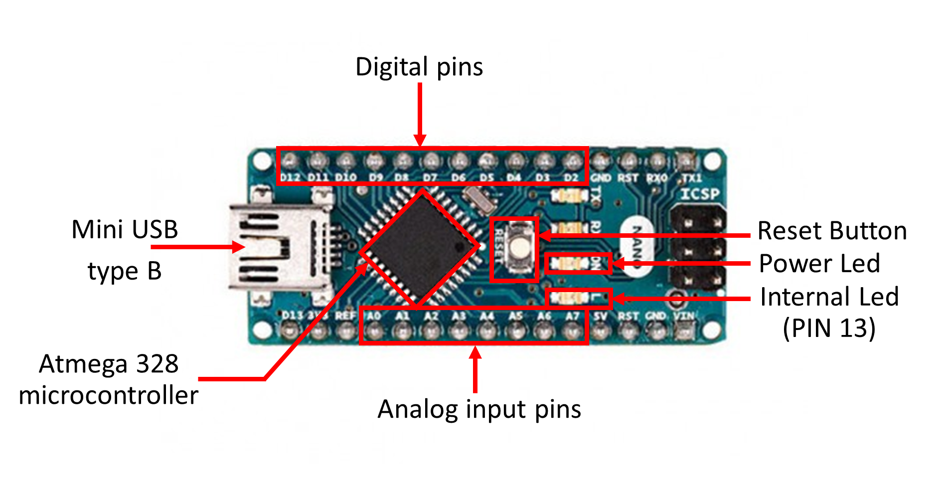
Next up is the Arduino Nano, this little fellow has a compact size of 18mm x 45mm compared to the UNO, which has dimensions of 68.6mm x 53.4mm. This is advantageous form factor for applications where the space available is limited. In addition to 14 digital, I/O pins, it comes with 20GB, all integrated into 30 header pins and includes the functionality of A6 and A7 pins. A compact PCB layout is enabled by the inclusion of a mini-USB connector for streamlined connectivity powered by the ATmega328P microcontroller running at 16MHz.
– USB Connector
The Nano features a mini-USB connector, USB 2.0 compatible, with data transfer at a speed up to 12Mbps. This configuration provides faster upload speeds and easy serial communication through separate D+ and D- lines. The mini-USB connector of the Nano takes advantage of the increased PCB space utilization compared to the Type-B connector of the UNO. Reliable connectivity is guaranteed with an integrated CH340 chip.
– Power Jack
The Nano has no dedicated DC power jack but it does have a VIN pin that the 6-12V input plugs into. With an on board AMS1117 regulator delivering a stable 5V output, the SMBJ5.0VTV6 is both USB and external power source capable. A resettable fuse provides circuit protection. Nano prioritizes power efficiency and ensures reliable power connections, reducing the risk of system instability, which makes it especially suitable for lightweight projects.
– Analog Pins
With 8 analogue pins of resolution 10 bits, the Nano surpasses UNOs 6 analogue pins. With this expanded analogue capability including pins A6 and A7, project possibilities grow. Analogue inputs have an up to 50mA tolerance. ADC data reading is enabled through an integrated multiplexer thus attaining efficient ADC conversion. The real-time sensing application and the sensor compatibility are supported by this functionality.
· Difference Between Arduino Nano And Arduino Mega!
– Size
With its small footprint (45mm x 18mm) the Arduino Nano is perfect for projects that are space limited, whereas the Arduino Mega (101.52mm x 53.3mm), is more suited for larger projects.
– I/O Pins
The Arduino Nano has 22 GPIO pins, enough for most projects. On the other hand, the Arduino Mega provides more allowing interfacing options due to its 70 GPIO pins allowing easy integration with more peripherals.
– Memory
For basic projects the Arduino Nano has 32KB Flash memory, 2KB SRAM and 1KB EEPROM. The Arduino Mega offers 256KB Flash memory, 8KB SRAM and 4KB EEPROM, for more complex code and data for more demanding applications.
– USB Connector
The Arduino Nano (Mini-B USB) and Arduino Mega (Type-B USB) support serial communication, firmware updates, as well as other serial communication. The smaller Nano connector works well for portable applications; while the solid Mega connector fits well for applications with demanding environments and reliable data passing.
Understanding Arduino Nano’s Memory Types!
· Flash Memory
The storage of program and operational stability has its guarantee in Secure nonvolatile flash memory. It has a 32KB capacity, dedicating 2KB to core functionality and bootloader of Arduino Nano which allows for easy code upload.
· SRAM
SRAM, in the form of volatile memory that is 1216 2 KB of high-speed memory for the purpose of temporary data storage during program execution. It’s rapid and efficient data processing and program operation that the memory makes possible.
· EEPROM
1 KB of non-volatile memory in EEPROM is available for persistent storage of such as calibration settings and user configurations. The memory stores critical information with power removed.
· Bootloader
2KB of flash memory is used by the bootloader to simplify the code uploading and firmware updates. It handles USB communication and a programmable initialization.
| Memory Type | Size | Usage | Type | Write Cycles | Access Time | Retention |
| Flash Memory | 32 KB | Program Storage | Non-Volatile | 10,000+ | Moderate | 20+ Years |
| SRAM | 2 KB | Variables | Volatile | Unlimited | Fast | Not Applicable |
| EEPROM | 1 KB | Data Logs | Non-Volatile | 100,000+ | Slow | 100+ Years |
| Bootloader | 2 KB | Startup Tasks | Non-Volatile | 10,000+ | Moderate | 20+ Years |
Table on Understanding Arduino Nano’s Memory Types!
2D Model And Dimensions Of Arduino Nano!
· Length
The compact length of the Arduino Nano of 45mm lends itself well to being integrated into a whole host of projects. This compatible with breadboards and lots of electronic components due to its thirty male header pins, arranged in two rows with a standard 2.54mm pitch. This design helps in organized circuit construction and prototyping.
· Width
The Nano is only 18mm slim, thus needing very little space to occupy. It has an arrangement of thirty header pins spaced at 2.54mm, which should be enough for connection to peripherals, sensors, displays, etc. This configuration accommodates a multitude of applications, from simple input/output operations, to multi sensor network.
· Mounting Holes
Despite no dedicated mounting holes, the Nano is very stable. Its FR4 material is a 1.6mm thick PCB which offers enough rigidity for secure integration into projects. Screws or standoffs as stable mounting on different surfaces are possible by using header pins.
· USB Connector
The only interface for power and programming is provided through the integrated, Mini-B USB connector. A reliable chip, the onboard CH340G USB-to-serial converter, allows you to write data onto the Arduino and read data from the Arduino directly through your computer. This provides an efficient means to upload a program, debug and serial data transfer to diverse applications.
Conclusion
The Arduino Nano Pinout optimizes project timelines through efficient resource allocation. Streamlined circuit design and implementation are facilitated by the Arduino Nano Pinout, minimizing errors and yielding superior outcomes. Use of the strategic tools improves on the development of the project. For all your projects explore HanuSEO comprehensive resources.

